PULSE DECAY THERMAL CONDUCTIVITY DEVICE
Currently, there are several ways in which thermal conductivity can be calculated or assessed on a given material. However, with each method of testing comes potential limitations such as size, material state, complexity, and time. The goal of this study was to develop a pulse heated thermistor that would reduce all four limitations, thus provide precise and timely results regardless of the material state and size. A thermistor is resistor which changes resistance in accordance to temperature. To achieve the design, heat transfer and electrical methods were applied. As with all resistors, heat is dissipated across the element and released into the surrounding environment. With this idea, the thermistor can be introduced with a large voltage, causing its resistive element to overheat and thus reduce its resistance. To manufacture such a device insulative material was added to prevent heat dissipation in the wrong direction. To achieve precise results, test specimens were required to be prepared to reduce the effects of ambient convective heat transfer. Measurement times after pulse were shown to have best results after seven seconds due to the thermistor achieving a steady decay of temperature back to equilibrium. Water was observed to have a thermal conductivity value of 0.613 W/m-K, within 5% of its accepted value. The results were obtained within five minutes, exceeding the fifteen-minute requirement. With the results obtained, it is conclusive that the device is functional and precise.
Keywords: <Thermistor>, <Conductivity>, <Pulse-Decay>
REQUIREMENTS
Fit into a 18" by 13" by 10" box
Provide information for calculations in under 15 minutes
Test bulk samples of solids and liquids
Be within 5% accuracy of literature values
Have a weight under 20lbs
Replaceable parts are easily located
Handle an AC source of 120V/60Hz
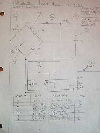
Circuit Analysis
Presented is a circuit analyzed for failure in a thermistor. Since thermistors are resistors that change their resistance with respect to temperature, it is necessary to determine if the thermistor will fail due to over loading on the circuit. The calculations presented show the thermistor will not fail due to overloading.


FEA ANALYSIS
Testing the project in Autodesk Inventor Nastran
The following is a memo addressing an FEA analysis of a Pulse Heated Thermistor for Senior Project Design. The model is designed to simulate the effect of the thermistor under a pulsing voltage.
The analysis was conducted using a Nonlinear Transient Heat Analysis. The loading is Heat Generation, which is applied to the simulated thermistor bead. Calculated from previous analysis, the load is approximated to be 3.18 mW per unit volume. The second load is an initial condition, applied to the surface contact between the simulated thermistor and simulated container of water. In this simulation, the assumption is that the water is at 18 degrees Celsius, and the thermistor is at equilibrium with the material.
In order to simulate transient heat transfer, time steps were decided to be 200 steps of 0.1 seconds. This would simulate a pulsing heat of 20 seconds.
In the assembly, the material of the thermistor bead is assumed to be the Autodesk libraries for glass (Conductivity = 1.38mW/mm-K), and the Autodesk library for water (Conductivity = 0.58mW/mm-K).
The mesh size was 0.508mm operating under linear constraints. The number of elements was 935572 with 156934 Nodes.
ANALYSIS SUMMARY
Analysis one utilizes given inputs of analog data to be computed. The inputs were optimized to work with circuit components to provide a given output. The outputs designated in analysis one, were then used to finish other analyses. The power output at a given voltage is in was used to calculate a radius of thermal insulating silicon. While the radius is small, the calculation was necessary to reduce the error of interference in data collection, which would result in an error. Next, the thermistor probe was analyzed for tolerance values. Given theoretical numbers, the conductivity value "k" was computed and compared with known literature values. The final installments of analyses are to compute a failure force of the thermistor probe in the silicon/syringe housing. Optimal contact with solid materials is a requirement, which requires ample force of the probe on the material it is testing. The scope of testing is to ensure that the thermistor provides a precise decay of temperature in the medium it is testing. The precision must be within 5% of known literature values and the accuracy will be tested with multiple trials of the same material. As such, the evaluation will be determined on a pass/fail basis, with the resulting conductance values being averaged together and compared to known literature values. If the values are within a 5% tolerance, the test is considered a success and the sensor passes.
METHODS
This project was provided by Dr. Choi, a professor at CWU. The device was analyzed and constructed in an apartment complex with limited access to resources. This is of course because of the COVID-19 epidemic of 2020. Within the constraints of space and proper machinery, the devices parts are to be outsourced to various companies. In this vein, circuitry parts cannot be machined or manufactured and must be purchased outright. Other parts, however, will be made in house either at CWU or using common everyday house tools. Other common parts such as hardware items will be outsourced to local Hardware stores in Ellensburg.
The convenience of minimal circuitry than the LabView configuration makes this an excellent choice. In an attempt to automate the analog data, an Arduino Uno was chosen for the code to output analog data can be monitored by either a computer of the user on a given LCD screen. In an effort to minimize the risk of disassembling the device in the event of failure, a modular design has been chosen. This means the circuitry can be removed easily be the user, and replaced with a cache of spare components. In the event of a failure of the thermistor, a second probe is included, which can be used immediately.
METHODS & CONSTRUCTION
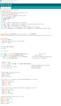
An introduction in Arduino Code

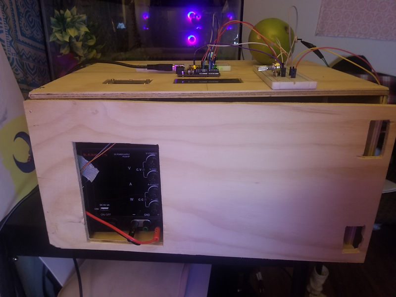
CONSTRUCTION
The construction of the device will be completely in-house except for one machined or made part which is 20-001. 20-001 is an ABS plastic print intended to house the thermistor for testing. The circuitry will be assembled with soldering and heat shrink tubing for insulation against convective agents. Housing the circuitry is a balsa wood box (20-002 through 20-007) which is fastened with hinges located on top of the wood, ensuring the circuitry can be accessed easily, as well as hold spare parts as needed. The circuitry, after being assembled and tested for results, will be placed inside of the box assembly and fastened using brackets. The long thermistor probe (20-001) will be fed through an opening and fastened outside of the box, for ease of access in the event of testing.
The first sub assembly to be completed will be the thermistor probe housing. This task is the most important to maintaining the strength and integrity of the thermistor prior to testing and calibration during the construction process. The probe sub-assembly will be electrically insulated with a resin compound. This further secures the thermistor to the probe for testing, while mitigating the risks of ambient air which drives forced convection. The leads need not be soldered as the connection with the jumper wires are designed to be unplugged. The second assembly is a circuit compilation, consisting of several electrical components. The power supply will have two outputs, one being a 5V DC supply to an Arduino Uno R3. The leads from the other output will connect to a timer switch which will be triggered for the duration of the pulse. The Arduino will output either to an LCD display screen or the serial monitor on Arduinos operating system. The components inside the assembly will be the wire leads extending from the thermistor, attached to the main aspects of the other circuitry. The thermistor bead will be held in place with epoxy to limit movement on testing of solid materials. Once the circuitry is assembled, it will be bracketed in place within the housing of wood, and the AC-DC power supply will be plugged into a 120V AC outlet. Now that power is connected, calibrate the potentiometer so that the bridge voltage on the circuit is balanced. From there turn the power supply on and begin testing. The device well report information sufficient enough for conductivity calculations within 30 seconds from power supply power up.


DESIGN AND TESTING
The thermistor pulse decay method is the approach to be conducted in this device. It requires understanding density and specific heat of the material prior to testing. The pulse decay method utilizes a thermistor placed in a probe. The thermistor is then introduced with a current that initiates a heating mode which causes the thermistors bead core to increase in temperature. This increase of temperature at the bead is proportional to the heat entering into the material it is testing, assuming the bead is uniformly distributing heat amongst its radius. It has been shown in Chen et al. (1981), that the current to cause heating in the thermistor must last around three to ten seconds. This is denoted as the pulse time. After the pulse is over, the thermistor is placed in a sensing mode, where the temperature of the bead is recorded for a time.
The two equations used in this study were established by Chen et al and Holmes. Equation 1 governs under the assumption of an infinitely small probe whereas Equation 2 was derived from Equation 1, but sought to eliminate some assumptions made in Equation 1.
These values are plugged into the these two equations separately to solve for thermal conductivity. The new thermal conductivity values are compared with a known conductivity value and evaluated for accuracy and precision.


TESTING PROCEDURE AND METHODS
An in Depth Introduction
Test procedures are broken into two phases, before and during testing. Prior to testing, the bridge circuit was balanced by adjusting the potentiometer. Next, constants must be established. The Density and Specific Heat of the specimen must be known before testing. Finally, establishing a pulse duration (tp) and measurement time (t) will conclude the constants prior to testing. Power across the thermistor element must be calculated and thus the thermistor must be engaged in both heating and sensing mode. By measuring the current across the thermistor in heating mode, power delivered is calculated.
During testing, a current is induced across the thermistor that causes the thermistor to start a self-heating phase. During this phase, the thermistor received the current for three to five seconds and then a timing switch stops the current from flowing across the bridge. Once the current had ceased, the Arduino will power the bridge and the thermistor will begin sensing-mode. During this phase, thermistor resistance was recorded for a period of five to fifteen seconds.
The Equations 1 and 2 are compared to both each other and the known value for thermal conductivity. This way the assumptions used in both equations are compared and evaluated.


ANALYSIS OF RESULTS
In conclusion, the device can perform evaluations on liquid like materials with an accuracy within +/- 5% error. Issues with testing solid materials occurred and cannot be recommended for the current device. Thus, further research into this phenomenon is required. Also, the second equation developed by Holmes is more applicable for the design of the probe, as it proved to be more accurate than Equation one. There appears to be strong dependence on time for the parameters of this testing and thus should be chosen with caution when selecting a consolidation period provided by the graphs of temperature decay versus time. Overall, the device is successful in reporting thermal conductivity as there is a mode of heat transfer between the thermistor and the medium it is testing. Further research into the efficacy of the device is in order for further experiments.
Therefore, it is suffice to say that the device functions by providing valid data insinuating a mode of heat transfer between the probe and the material. However, the accuracy of the device required several trials to be conducted as results maintained were variable between trials. It is suffice to say that the device is functional but is inefficient in the data it provides.

BUDGET
There is a total of 15 parts needed for the construction of the device. Procurement of the most expensive parts, All 55 Series items are purchased online and 20-002 through 20-007 was procured locally. A large amount of parts in the device will be outsourced. This is largely due to the COVID-19 epidemic that effects the U.S in 2020 and is projected to last through the 2021 school year. This hinders ability for Central Washington University (CWU) students to access the machining labs on CWU’s campus. Projected labor costs are compiled using the median average for mechanical engineers. Estimated costs of parts for the project is $400.00 and labor is $6,887.00 bringing the total to $7,287.00. Funding for the device will be internally provided. Currently, roughly only $300 of the budget has been used and it is likely that the project will go under budget.
PROJECT MANAGEMENT
Introduction
This project will succeed due to the availability of technical expertise, resources, and time constraints. These areas encompass the least amount of risk for the duration of this project. Technical expertise or expert in the field is consistently available at CWU. The resources to construct and test the device are readily available. Time is the amplest because of the access to work-in-home due to COVID-19. Some areas of higher risk include budget and material acquisition.
Human Resources
The principal engineer will provide analyses in all aspects of the project, the construction, and the testing of the ending design and their resume is shown in Appendix H. Other human resources are Professors Charles Pringle and John Choi. Their expertise will aid in the completion and success of the project. Another resource is the other engineers Kyle Saafeld and Lucas Hill who are working on similar projects. With the resource sharing between engineers and the guidance of the Experts, the project will continue unhindered.
Physical Resources
Physical Resources are the processes and machines that will be utilized to complete the project. Among these resources, the most critical is the Makerbot 3-D printer that CWU will provide. This printer will create the thermistor housing which is necessary to produce a reasonably priced and tight tolerance housing for which the thermistor will reside and provide data for testing. Other minor resources will be the tools available at home. These include a jigsaw, screwdriver, hand drill, soldering iron, etc.
Soft Resources
Soft resources are limited to two types. Excel for data acquisition and analysis as well as Solidworks which is provided by CWU. Solidworks will provide drawings to be printed and modeled. Arduino's Programming Software will also be used. It is a free to download software.
Financial Resources
The project sponsor will be the principal engineer and provide monetary support to aid in the completion of the device. The equipment will also be provided by the principal engineer as well.
SCHEDULE
The Pulse Heated Thermistor must be completed by the last week of the third quarter at Central Washington University. Potential risks to prevent milestones from being completed on time are lead times on specific parts and loss of progress due to revisions. The following is a list of Major Deliverables by time:
Designs Finalized by November 20th, 2020
Construction Completed by March 5th, 2021.
Testing and Results Completed by May 7th, 2021
Final Report and Presentation by first week of June, 2021

DISCUSSION OF SCHEDULE
The design process went smoothly and no setback occurred during the time. This portion of the project was completed on time.
Construction of the device has shown mild set backs and successes. Currently, the most difficult part of the construction of the device has been finished as of February 19th, 2021. The Circuitry has proven challenging and has required more hours of work than thought of. The initial anticipation of completion suggested that the work would be completed by February 26th, however as setbacks occurred, the timeline had to be pushed back.
Testing of the device has remained on schedule and proven successful. The device is functioning properly and producing results. The device had completed its testing phase on May 7th, 2021.
DISCUSSION OF PROJECT DESIGN
The project initially began as a simple idea, consisting of a thermistor attached to a power supply and a resistor in series. During this first conceived idea, the device, and its evolution, were still in their infancy. By studying the thermistor and the properties associated with the thermistor, the initial idea was to introduce a heating current and measure the resistance of the thermistor when the current had ceased to flow at a high voltage. As time progressed and more research was conducted on the thermistor properties and the thermal properties of conductivity, it became more apparent the initial simple circuit would not work. This is where the first initial circuit became obsolete and was replaced by a bridge circuit acting similarly to a voltage divider. Through analyses and studying of Chen 1981, a new circuit which reflects the success of previous devices is to be used. This same circuit introduced modern parts which can be programmed for time, an important variable when testing for thermal conductivity. In these aspects the project evolved to operate well in the tasks it is designed for. The other aspects of design, which became a problem, was the conception of the housing for which to thermistor would be housed. In previous designs, the thermistor was placed into a syringe and fastened with an insulating epoxy. The initial design concept was to place the thermistor into a syringe as well, however, the syringe must be cut radially to very tight tolerances for the bead to be accessible to the material it would be in contact with. Another problem arose as well. The previous designs which were conceived before this device were designed to only test liquid or gelatinous materials. This is a problem in the design because as per the requirements, a solid metal material must be tested as well as liquid. Force must be delivered into the thermistor to optimize connection with the material to be tested, as well as reduction in ambient convection. After careful consideration, the concept was changed for this device to include a 3-D printed thermistor housing. This reduced waste by not purchasing large amounts of syringes, but also kept the tolerance of the radius of the housing lower. Lastly, the circuitry housing was conceived to allow access to the circuit for balancing. Initially, this was a wrong design. The housing was first conceived to be a closed box with minimal access to internal components. However, as new information began to be understood, the design had to be changed. The design encapsulated the idea that the internal circuit components must be balanced prior to use as well as replacement parts had to be accessed in case of failure. The final design became a housing of balsa wood with hinges that allow easy access to internal
DISCUSSION OF CONSTRUCTION
Construction has been successful with respect to the rigorous design process and minimal machining challenges. The circuitry is operating withing parameters and has been successful. The major setback with the construction process is with the programming of the Arduino. In order to work the Arduino, an understanding of the C coding language has too been applied. An initial code has been written and must be tweaked extensively prior to the final device turn in.
Another issue has arisen in the specification of the leads on the thermistor (55-003). The leads do not have the same gauge of wiring consistent with the jumper cables that were purchased. The voltage capacity of the gauge is unaffected by the amperage flowing through the wires; however, the connection is more of an issue. The thermistor leads have been positioned into the jumper cables and have established an adequate connection. The risk of the leads being removed is also mitigated in the sub-assembly of the thermistor housing.
In an effort to change the design, the material for the housing was swapped for a durable but lightweight ply wood. The wood was economical, saving money in the budget and still fulfilled the weight requirement of 20lbs. Another revision in the design was altering the shape of 20-001. The small cylindrical shape caused difficulty in the pouring of insulating resin into the house. The change widened the cylinder at the end where the thermistor leads are placed
DISCUSSION OF TESTING
An issue with the device concerning the resolution of the device was discovered. It is apparent that the Arduino board either cannot compute the resistance of the thermistor during pulsing or the thermistor does not undergo heating during pulse. This is seen while graphing the entire experiment after acquiring data via the serial monitor software on Arduino IDE. While looking at the graph to notice any potential pulse decay, there is an extreme drop-off of temperature after pulsing. In a perfect experiment, the decay would take place over the time from of two to three seconds. While analyzing the graph it is apparent that noise is evident for the drop off temperature in the 50-millisecond range of data acquisition. Certain additions to the device were conducted to check if the thermistor is heating up properly. A 20V DC pulse was induced onto the thermistor and temperature was analyzed after the pulse. The thermistor gave no evidence that it had heated up during this experiment.
To remedy this situation which resulted in no mode of actual heat transfer occurring, the Code and Circuit were adjusted. This included a new switch for the voltage reading and a PWM configuration for the code to protect and reduce noise during pulsing. The remedies worked, and ample temperature decay with respect to time is found.
CONCLUSION
The device is functioning and works as intended. The thermistor under pulsing voltage heats to a degree, then a decay of temperature to equilibrium is achieved. Despite minor inconveniences such as overloading the first Arduino and difficulty producing a circuit which delivers tangible results, the construction portion was completed on time for presentation. The addition of the LCD interfaces aids in a sleek but practical design. The device meets certain requirement such as a final size of 18in x 13in x 9.75 and a weight of 11.8lbs. Two probes were created, satisfying another requirement. In conclusion, the device is functional, meets specific requirements, and is ready to be tested.
A handful of improvements and further research to the device is needed to further establish the efficiency and scope of the device. Firstly, the thermistor probe is required. An improved design to the probe would aid in the processing of solid materials like the apple tested. Secondly, more trials conducted with the device on multiple different materials are needed as well. Improving and analyzing the issues with the Pulse Decay Method to compute thermal conductivity with solid materials that maintain high thermal conductivity values. Lastly, sleekness of design to improve portability. While the Arduino acquisition software is helpful to the design, being limited to a computer to analyze data is a hinderance. A suggestion to future designs is the exchanging of higher voltage batteries to power both the pulsing and sensing mechanisms would improve portability. For further research and continual improvement of the design, it is sufficient to suggest that once the issues regarding measuring thermal conductivity of highly conductive materials, further research into the conductivity of biological mediums such as skin and other organs is necessary.
Overall, the Pulse Decay Thermal Conductivity Device is a partial success. It satisfied most criteria excluding the thermal conductivity measurement in one experiment. It is function and precise in the testing of liquid state materials like water, while maintaining difficulty with solid state materials. In future research and processing of the device, it would be sufficient to conclude that a handful of changes to the project are needed to improve accuracy and design functionality
